This article will help you gain an intuitive understanding of CAD scale factors and best practices for scaling design drawings. We will be using examples from AutoCAD, but the same steps can be similarly applied in most CAD software.
What is a CAD scale factor?
The scale of a drawing can be described and applied in a few different ways. It can be metric or imperial, it can be a ratio with or without units, and it can be written in the format of 1:n or n:1.
The particular convention used will depend on the standards of your country (metric vs. imperial), the profession (architecture vs. engineering), and the context of the drawing (a detail vs. a site plan)
Despite these differences in notation, the rules governing all scaled drawing are the same. Computer Aided Design (CAD) makes it simple and effortless to move between scales and to produce drawings at multiple sizes with the help of CAD scale factors, provided you understand how to apply them.
Design work today happens at full-scale; that is, while designing in a digital space you are drawing life-sized objects. But a full scale drawing is not often very useful outside of AutoCAD, Vectorworks, or your CAD software of choice.
On paper and on screens, our drawings need to meaningfully represent our ideas at scales that are legible and manageable for clients, builders, and our peers.
This article will use common imperial architectural scales in its examples, but you should be encouraged to familiarize yourself with metric and engineering scales so that you can intuitively move between them with the help of CAD scale factors- an important skill for our increasingly interdisciplinary and globalized profession.
Scale Factor vs. Scale
A scale factor is a ratio of change from a drawing to real life. Typically, a scale factor is unit-less; a scale factor of 48 (or 1:48) is saying that for one unit on the page, it represents 48 of the same units in real life.
This is a bit different than a scale; an imperial scale is described as a ratio of inches-to-the-foot. Because of convention, and because of the nature of imperial units, it is often more meaningful to tell the reader of the drawing that ¼ of an inch on the page represents 1 foot in real life, for example. This would be notated as (¼”=1’)
While the two previous examples may look a lot different, they actually could be describing the same drawing. In our example, 1:48 means that 1” is equivalent to 48” on the ground, which is another way to say that 1” is equivalent to 4’. Our scale of (1/4”=1’) is saying the same thing, but is displayed as a fraction and with incongruent units; if we multiply by 4 to reduce that fraction to a whole number, we get (1”=4’).
They’re two very different ways of saying the same thing- that the drawing is 48 times smaller than life.
So why is there a distinction at all? A scale factor is more useful for calculating measurements between different scales- you don’t have to worry about units, the conversions are easily inputted to a calculator, and they interface nicely with CAD software.
Conventional notation for the imperial scale, on the other hand, carries over from the days of manual drafting and the scale ruler.
As a convention, it has stuck around in our discipline and continues to be the most useful notation for quickly dimensioning a printed scaled drawing.
Metric Scales and Engineering Scales
Metric scales are a bit different; because metric units are a base 10 system (that is, 1 meter=10 decimeters=100 centimeters=1000 millimeters), metric scales are able to effectively do away with units entirely and still be easily understood.
Metric scales are represented directly as unit-less scale factors (such as 1:50) because the conversions between metric lengths are all factors of 10. A metric drawing will indicate its scale factor, and the unit it was drawn in.
Remember, the numbers on each side of the ratio represent the same unit.
Imperial engineering scales function the same way as imperial architectural scales, but their notation standard is slightly different.
An engineering scale would be shown as 1”=20’, or another multiple of 10 feet; this is partly due to the fact that they usually work in decimal inches rather than fractional inches. Common imperial engineering scales are shown in the next section for reference.
CAD Scale Factors Chart
Within the design community, there are some loose conventions around choosing a scale for a given context.
While these standards do not apply in every situation, it is agreed that a 3”=1’ scale is often appropriate for construction details, while 1/16”=1’ is appropriate for a site plan, and so on.
Deviation will always occur, but the following guidelines for scaling a drawing are a good place to start. It is also recommended that you avoid using a-typical scales because many designers have an intuitive understanding of what (3/4”=1’) feels like.
If you’re bringing a drawing to a potential employer that is scaled at (7/16”=1’) or at (1:325), you may introduce a moment of illegibility and confusion that could hinder communicating your design.
Imperial Scale Factor
How to convert scale in Autocad?
Generally, drawings in AutoCAD and other CAD software are drawn at 1:1 scale- that is, life size. Occasionally, we end up with files that are out of scale, and this should be resolved before any further paper space scaling occurs. Incorrectly scaled drawings often happen when importing CAD files that use a different base unit than you, opening scaled drawings (i.e. a PDF sent by a colleague), or simply by human error. Fortunately, it’s easily resolved and is the first step to converting between scales in AutoCAD. After your content is brought to full scale in the model space, you simply need to select your desired “Viewport Scale” for each viewport in your paper space layout.
Getting to Full Scale
- In the Model Space, measure points and compare them to their annotations to get a sense of what is wrong.
Does the content need to shrink or to be enlarged? By how many orders of magnitude? Run the (UNITS) command- what “Insertion Scale Units” is AutoCAD telling you it is in? What is your “Length Type”? Are you looking at a file that is in a highly reduced paper scale, at full scale in the wrong unit, or something else? Having your head around where you are, and where you want to go, will do wonders for making the scaling process simple and clear.
Find a known measurement in the drawing using an annotation or an object of standardized size, such as a 4’x8’ sheet of wallboard. Once you have identified a line of known length, we are going to say a door expected to be 36” wide in plan, measure the length in model space using the (DIST) command. For this example, we will say that Autocad reports back that the door is 91.44 inches wide. You have two easy options from here to correctly scale your drawing:
Reference Scaling
- Select all the content of your drawing and enter the command (SCALE)
- Select a base point
- This is going to be one edge of your known distance: the door’s width
- Enter (R) to activate reference scaling
- Select two points for a reference length
- In this case, your first point will be one edge of the door width, and the second point will be the other edge. Now the line is referenced at 91.44 inches
- Enter (36”) as the new length
The entire drawing will rescale, so that the door is the correct 36” wide
Unit Conversion and Scale Factors
Before scaling the drawing, however, you may have noticed that 91.44 seems to be about 2.5 times larger than 36 and connected the dots that the content was likely drawn in centimeters. Checking that 36” is, in fact, 91.44 cm confirms this. At this point you could scale your drawing using a scale factor.
- Select all the content of your drawing and enter the command (SCALE)
- Select a base point
- Enter the scale factor
- Rather than entering reference mode as before, you will simply enter the scale factor of Centimeters to Inches: 1/2.54 or 0.3937. This will re-size your entire drawing to be accurately scaled to inches.
Before you move on, check that your file is configured to continue using the units you intend with the instructions below.
-DWGUNITS
(-DWGUNITS) is a powerful command that is used for changing the units of an AutoCAD file. It can also be used to skip the step above and scale the drawing from one unit to another.
Using this command is a good idea, particularly when you are bringing in a file of dubious origin where dimensioning best-practices may not have been observed. This command allows you to change unit settings in your file and, optionally, to scale the file for those units
To avoid future scaling headaches, I always find it to be a good idea to run through the (-DWGUNITS) command after I have manually re-scaled a drawing to ensure that my units are configured correctly.
Converting From One Scale to Another with CAD Scale Factors
Typically in AutoCAD we don’t need to convert between paper scales manually, but there are situations where you would need to. If you are using CAD software that doesn’t separate a model space from a paper space, or if you need to quickly resize a scaled drawing for plotting, etc, you can move between scales using CAD Scale Factors.
Determine Current Drawing Scale
****Let us say you have a wall annotated at 24’- you check the length of the wall using the (DIST) command in AutoCAD and find that it is drawn at 3”. What is the current drawing scale?
- Based on our measurements we have a scale of (3”=24’). To convert this into a typically notated scale of n”=1’, divide both sides by 24.
- 3/24” = 1’
- Reduce the fraction of 3/24 to 1/8
- The new scale is (⅛”=1’)
- Now, to calculate the scale factor, you’re going to invert the fraction and multiply by 12.
- (8/1) * 12 = scale factor of 96
Determine Target Drawing Scale
One way to pick a new scale is to determine your minimum scale factor. Let us say you have 240’ of site to represent, and 16” of paper to show it. What is the minimum scale factor that could fit all your content on one page?
- Divide the largest length of your design (in feet) by the length of paper you have to work with (in inches) and multiply by 12.
- (240’/16”) x 12 = scale factor of 180
- You must use a scale factor larger than 180 to fit your content on one page- at this point, consult a chart above to pick a scale.
- In this case, we’ll pick 1/16”=1’.
- Invert the fraction and multiply by twelve to get the target scale factor
- (16/1) * 12 = scale factor of 192
Calculate New Scale Factor
Our original scale factor is 96 ((1/8=1)) and we want to size the drawing to a scale factor of 192 ((1/16=1)).
This one is going to be easy; we know the drawing should get smaller and so we can expect a scale factor of less than 1.
- Simply divide the two scale factors; with the original scale factor as the numerator and the target scale factor as the denominator.
- 96/192=scale factor of 0.5
- Our drawing is going to be scaled by a factor of 0.5, or zoomed to 50%
- Like before, we will select all of our content. Use the (SCALE) command and enter a scale factor of 0.5, giving us a drawing scaled to (1/16”=1’)
Calculating Scale Factors of Engineering Scales
To calculate the scale factor of an imperial engineering scale, just remember that you want to calculate “how many inches of paper to how many inches of real life”.
- Multiply the feet by 12 inches and you’ll have your scale factor.
- For a scale of 1”=40’
- 40 * 12 = scale factor of 480
History of CAD
CAD is unique from manual drafting in that it allows you to draw at full scale with precision. In fact- it was this ability to draw at full scale that was part of what made CAD so revolutionary upon its adoption. Full scale drawing has occurred since the beginning of human construction and planning; mystics, architects, etc, often planned villages and new buildings directly on the ground by using their knowledge of the landscape and people’s needs to etch instructions for buildings right in place.
Eventually, new construction techniques required new forms of abstractly representing buildings- to communicate, instruct, and record the details of construction. As materials and building techniques demanded ever smaller tolerances, technical drawings required more precision and descriptiveness. The advances of modern construction in architecture, product design, aerospace, cars, and more, paced forward hand-in-hand with advances in the tools available for designing and describing those objects. Whether you believe that advances in computer aided design occurred to keep up with a changing world, or that those advances in CAD opened the doors for advancing building technology, there is no doubt about the significant role that digital tools and computer aided drafting have played in transforming our discipline.
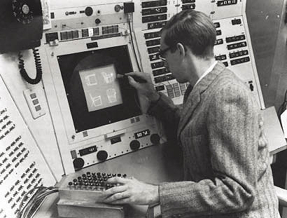
1960 - Sketchpad is developed at MIT
Sketchpad ran on one of the world's largest computers at the time, and is considered to be the first true interactive CAD program. Sketchpad introduced some of our most common contemporary CAD features: snapping to points, rubber-banding, instances, dynamic transformation, and more. While Sketchpad was a proof-of-concept project, it opened the door for what was to come in CAD.
https://www.designworldonline.com/50-years-of-cad/
1971 - ADAM
This interactive drafting and designing software was some of the first to be largely commercially successful and available on consumer home computers.
1972 - Synthavision by MAGI
The first 3D solid modeling software was intitially designed to analyze nuclear radiation exposure through solid buildings. The company's success at developing these tools led them to pivot towards 3D graphics modeling and eventually led them to produce the visuals for Tron in 1982.
1982 - AutoCAD
In 1982, AutoCAD v 1.0 was introduced into the world. It closely leaned from hand drafting techniques of the time, replicating many industry standards into a digital platform that would change the way architecture is practiced.
1987 - Pro/Engineer
In 1989, computer aided drafting became parametric with the introduction of Pro/Engineer.
1993 - NURBS
CAS Berlin devs first interactive NURBS modeler for home computers, called NöRBS. NURBS are spline defined surfaces where points in a 3d model control lines that ultimately control surfaces. This is the most common alternative to MESH based softwares.
Conclusion
Getting the hang of CAD scale factors can be a frustrating endeavor and doing them wrong can lead to some pretty embarrassing situations. When you are rescaling drawings, just remember: don't scale recklessly, and try to get a good understanding of what you intend to do. What are your units? Should your drawing get bigger or smaller? What is the current scale factor? If you can answer those questions, and follow the examples given in this article, you'll be a scaling master in no time.
And, if you're interested in improving other areas of your firm's performance, get started with Monograph today.